
Site Lighting and Photometrics: Why Full Cutoff Fixtures Keep Your Project Out of Trouble
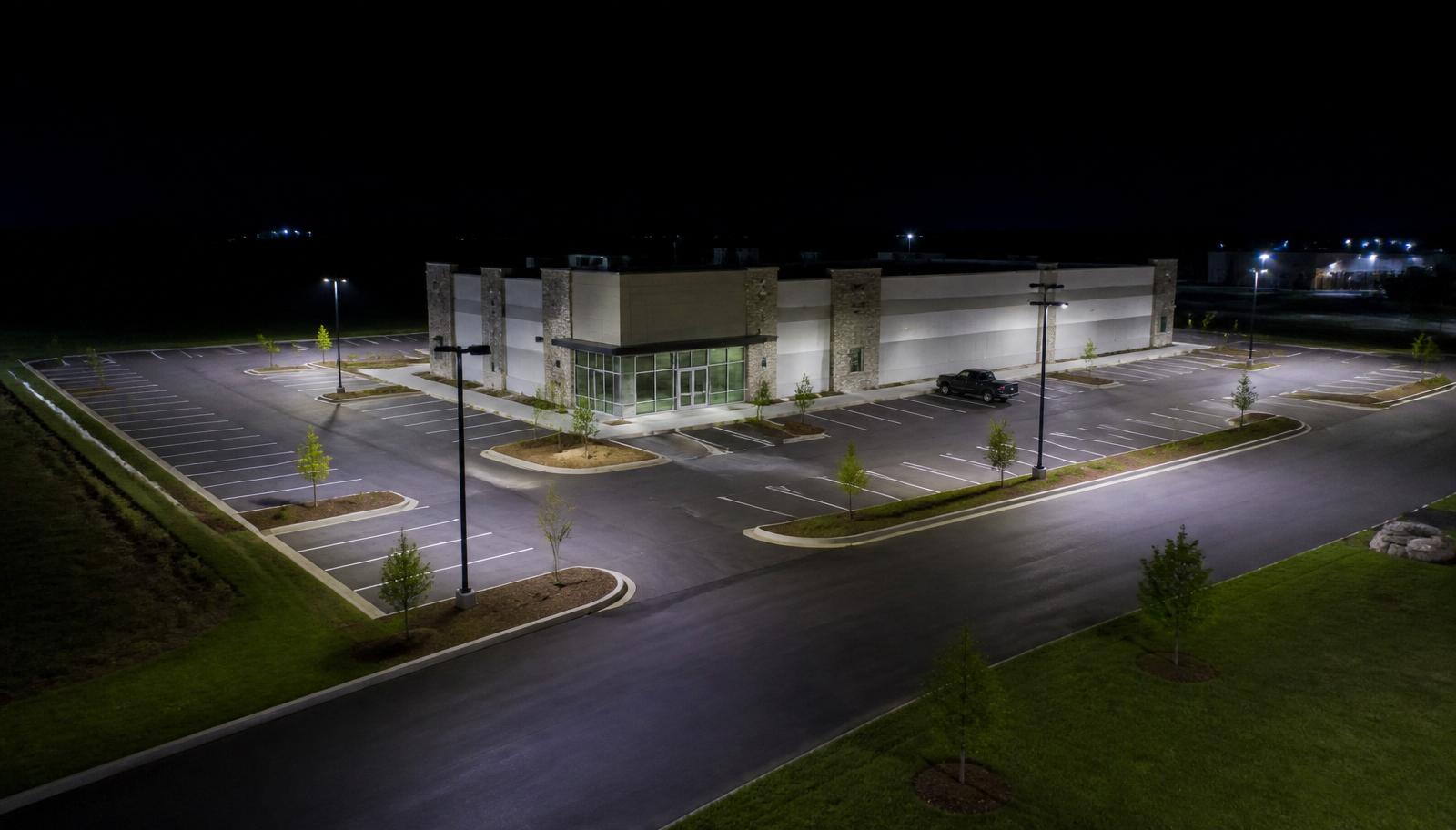
Site lighting is one of those scopes that looks simple on paper and turns into a fight in permit review. Pole heights, foot-candle averages, uniformity ratios, backlight/uplight/glare (BUG) ratings, and — the one that quietly kills projects — light trespass across the property line.
A proper photometric site plan is what keeps all of that defensible. It is not a marketing render. It is a calculated grid of illuminance values, produced from real IES files for the fixtures you're actually going to install, laid over the site plan with property lines called out.
What a photometric plan actually shows
At a minimum, a usable site photometric includes:
- A calculation grid across the entire site — typically 10' x 10' spacing for parking, tighter for drive aisles and entries.
- Average, minimum, and maximum foot-candles for each functional area (parking, drive aisle, pedestrian, entries, loading).
- Uniformity ratios (avg:min and max:min). This is what keeps a lot from having bright pools and dark valleys between poles.
- Illuminance at the property line — usually a separate line of calculation points at 0'-0" and sometimes 5'-0" outside the property line.
- Fixture schedule with mounting height, tilt, orientation, lumen output, wattage, CCT, and BUG rating.
If a plan is missing property-line values, it is not a photometric plan. It is a pretty picture.
The property line is where projects get held up
Almost every municipality we work in has some version of the same rule: illuminance at the property line, measured horizontally at grade, must be at or below a set value. Common numbers we see:
- 0.0 fc at a residential property line.
- 0.1 fc at a commercial or roadway property line.
- 0.5 fc at some mixed-use or non-residential lines.
These sound trivial. They are not. A single Type III shoebox at 25' with the wrong optic can throw measurable light 40'-50' past the pole. Multiply that by a row of parking lot poles and the light spillover across the back of a site can easily hit 1–2 fc at the fence — well over the limit, and very visible from the neighbor's back yard.
Full cutoff fixtures: what they are, and why they matter
A full cutoff luminaire (as defined by IES) emits zero candela at or above 90° from nadir (straight down), and no more than 10% of rated lumens between 80° and 90°. In plain terms: nothing shines sideways or up out of the fixture.
That single design choice does three things:
- It kills light trespass. With no light above 80° from vertical, the fixture physically cannot throw useful lumens onto the neighbor's yard. Property-line calculations drop, often by an order of magnitude, versus a semi-cutoff or drop-lens fixture.
- It kills glare. Drivers approaching the site are no longer looking at a bare LED source at 25' in the air. That improves safety and — practically — reduces complaints.
- It keeps the sky dark. Zero uplight means the fixture contributes nothing to skyglow. That is what almost every dark-sky ordinance (and a growing number of standard zoning codes) is actually asking for.
BUG ratings translate this to a spec you can enforce. A U0 rating means zero uplight — the modern equivalent of "full cutoff." Pair that with a low B (backlight) rating and a house-side shield where the pole sits close to the property line, and the trespass problem largely solves itself before it starts.
Where designs go wrong
Most site lighting problems trace back to one of a small set of decisions:
- Wrong optic for the pole location. A Type V (symmetric) distribution on a perimeter pole will throw light onto the neighboring property no matter what the pole height is. Perimeter poles want Type II or Type III with a house-side shield.
- Pole too tall for the setback. The taller the pole, the farther useful light travels horizontally. A 30' pole 15' off the property line is fighting geometry.
- Uplight from "architectural" fixtures. Bollards, wall packs, and up-oriented facade fixtures are the usual culprits on property-line failures. They are also the ones nobody photometrics until it's too late.
- CCT that reads as glare. 5000K parking lot lighting looks "brighter" and reads as more offensive from adjacent residential — even when the fc calc is compliant. 3000K–4000K is almost always the right call.
- Assumed IES files. Photometrics run off a generic "similar" IES file don't match the fixture that shows up on site. Always model with the manufacturer's actual IES for the exact optic, wattage, and lens.
What we deliver
For every site lighting scope, V3 produces:
- A stamped photometric site plan with a full calc grid, property-line points, statistics table, and fixture schedule.
- A fixture cut sheet package with BUG ratings and IES filenames called out so the AHJ can verify what was modeled.
- House-side shields, backlight control, and tilt callouts where the geometry needs help — not left to the field.
- Controls narrative: photocell + time clock or networked control, plus part-night dimming if the jurisdiction (or the operator) wants energy savings after midnight.
The takeaway
If your site lighting design starts and ends with "pick a pole and space them 100' on center," expect a redline. A real photometric plan — built around full cutoff, U0-rated fixtures, with property-line values calculated and shown — is what gets the permit stamped, keeps the neighbors quiet, and holds up when someone shows up with a light meter after the project opens.
That's the part we take seriously on every V3 site.
Have a project to discuss?
V3's licensed PEs deliver coordinated MEP design across Texas and beyond.
Start a conversation